
In the world of construction, we often say that a building is only as good as the paper it’s printed on. Before a single excavator arrives at a site, a massive volume of data must be translated into a visual language that contractors, craftsmen, and inspectors can understand. This language is the Construction Drawing Set.
To the untrained eye, a set of blueprints looks like a chaotic web of lines and symbols. To a professional, it is a precise, legally binding set of instructions. Understanding the distinction between architectural, structural, mechanical, and electrical drawings is not just a matter of curiosity—it is essential for budget control, safety, and project synchronization.
In this guide, we will break down the four pillars of construction documentation and explain how they work together to bring a structure to life.
1. Architectural Drawings
Architectural drawings are the starting point of every project. They define the “what” and the “where.” While other drawings focus on how the building stays up or how the lights turn on, architectural drawings focus on the user experience, aesthetics, and spatial functionality.
1.1 Floor Plans
The floor plan is a horizontal section taken at approximately 4 feet above the floor level. It shows the arrangement of rooms, the thickness of walls, the location of doors and windows, and the flow of traffic. For an engineer, the floor plan is the “master map” that all other disciplines must follow.
1.2 Elevations
Elevations provide a flat view of the building’s exterior from all four sides (North, South, East, and West). These drawings specify exterior finishes—such as brick, glass, or cladding—and show the vertical heights of the building, including floor-to-ceiling dimensions and roof peaks.
1.3 Sections and Details
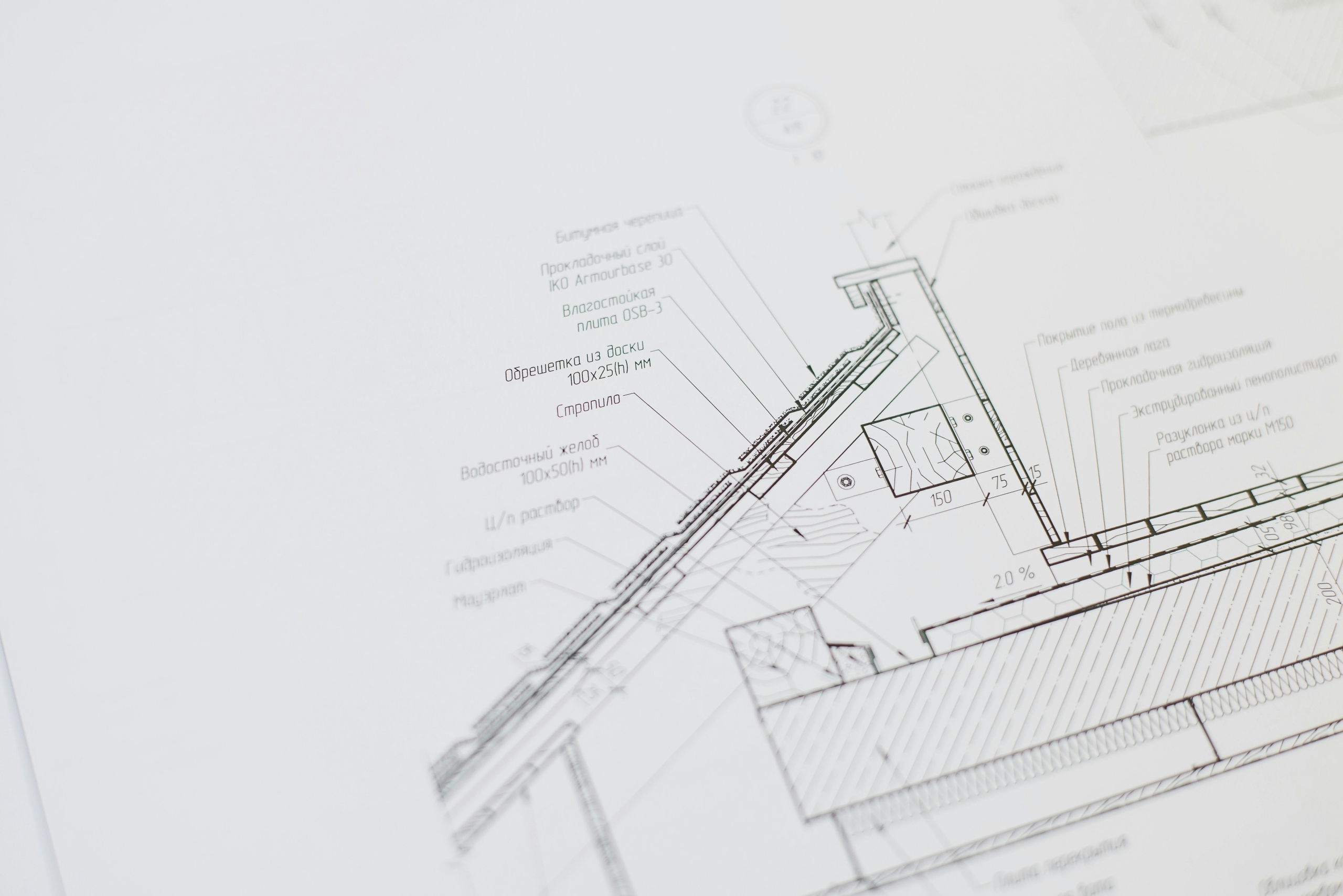
Sections are “cuts” through the building that show the internal layers. If you were to slice a house like a cake, the section would show you the thickness of the floors, the height of the stairs, and the relationship between different levels. Details are zoomed-in views (often at a larger scale) that show complex junctions, such as how a window frame meets a masonry wall.
2. Structural Drawings
If the architectural drawings represent the “skin” and “beauty” of a building, the structural drawings represent the “skeleton”. These drawings ensure that the building can support its own weight (dead load) and the weight of people, furniture, and environmental forces like wind and snow (live loads).
2.1 Foundation Plans
The foundation plan is arguably the most important sheet in the set. It specifies the type of foundation—whether it’s a spread footing, A raft foundation, or deep piles—based on the geotechnical report. It shows the placement of footings, grade beams, and the thickness of the basement walls.
2.2 Framing Plans
Framing plans show the layout of the structural members that support the floors and roof. In a steel building, this shows the beams and columns; in a wood-frame house, it shows the joists and rafters. Each member is labeled with a specific size and material grade (e.g., a H250x250 steel beam).
2.3 Reinforcement Details
For reinforced concrete structures, these drawings show exactly where the “rebar” (reinforcing steel) should be placed. It specifies the diameter of the bars, the spacing between them, and how they should be “lapped” or joined together to ensure the concrete doesn’t crack under tension.
3. Mechanical Drawings
Mechanical drawings, often consist of HVAC (Heating, Ventilation, and Air Conditioning), plumbing, and fire protection drawings, ensure that the building is habitable. They manage the climate, air quality, water supply/waste drainage, and specialized machinery.
3.1 Ductwork Layouts
These drawings show the path of the air ducts from the main air handling units (AHUs) to individual rooms. They specify the size of the ducts and the location of “diffusers” (the vents that blow air into a room).
3.2 Equipment Schedules
Mechanical drawings include tables called “schedules” that list every piece of equipment—furnaces, chillers, exhaust fans, and pumps—along with their required capacity.
3.3 Fire Protection (Sprinkler Systems)
In many jurisdictions, fire protection is included in the mechanical set. These drawings show the network of pipes and sprinkler heads required to suppress fire, as well as the location of fire hydrants and standpipes.
4. Electrical Drawings
Electrical drawings map out the distribution of power and data throughout the structure. These are highly symbolic and require a specialized legend to interpret.
4.1 Power Plans
This drawing shows the location of every electrical outlet, floor box, and heavy equipment connection. It also traces the “circuits” back to the electrical panel. For a commercial kitchen or a factory, these plans are incredibly complex due to high-voltage requirements.
4.2 Lighting Plans
Separate from power, lighting plans show the location of fixtures, switches, and dimmers. They also include the “Reflected Ceiling Plan” (RCP), which shows how lights are centered within ceiling tiles or architectural features.
4.3 One-Line Diagrams
This is a schematic representation of the entire electrical system, from the utility transformer outside to the smallest sub-panel inside. It doesn’t show physical locations, but rather the logical flow of electricity and the safety breakers in place.
5. Mechanical & Plumbing (MP) vs. Electrical (E): The MEP Coordination
In the industry, we group these as MEP (Mechanical, Electrical, and Plumbing). While they are separate drawings, they must be perfectly coordinated.
- Plumbing Drawings: Often grouped with Mechanical, these show the “Wet” systems. This includes the supply of potable water and the drainage of waste (sewer). It also includes specialized systems like medical gas in hospitals or compressed air in workshops.
- The Conflict: The biggest challenge in construction is “Clash Detection.” Imagine a structural beam, a large mechanical duct, and a plumbing waste line all trying to occupy the same 12-inch space in a ceiling. This is why MEP coordination drawings are vital.
6. Key Differences at a Glance
To help you distinguish between these sets quickly, refer to the table below:
| Drawing Type | Primary Focus | Key Elements | Who Prepares It? |
| Architectural | Aesthetics & Function | Room layouts, finishes, and heights | Architect |
| Structural | Safety & Stability | Foundations, beams, rebar, load paths | Structural/Civil Engineer |
| Mechanical | Comfort & Air Quality | HVAC ducts, units, and thermostats | Mechanical Engineer |
| Electrical | Power & Lighting | Outlets, wiring, panels, data | Electrical Engineer |
| Plumbing | Water & Waste | Pipes, water heaters, vents | Mechanical Engineer |
7. The Importance of “As-Built” Drawings
The drawings described above are known as “Construction Documents”—they represent the intent. However, during construction, things change. A pipe might be moved 6 inches to avoid a rock, or a wall might be shifted slightly.
At the end of the project, the contractor produces As-Built Drawings. These are the final, corrected versions of the blueprints that reflect exactly what was built. For a building owner, these are the most valuable documents for future renovations or maintenance.
8. Conclusion: Building on the Same Foundation
A construction project is like assembling a puzzle—every piece must fit precisely for the full picture to emerge. When design teams work from uncoordinated drawings, pieces clash, progress slows, and risks increase.
With BIM (Building Information Modeling) or carefully coordinated CAD files, Architectural, Structural, Mechanical, and Electrical disciplines align their work from the start. This alignment eliminates conflicts early, supports efficient construction, and ensures a smooth transition from design intent to a completed, functional building.